Lawerence Berkeley National Laboratory
Circuit Board Design
Each scintilator is connected to one phototube which is wired to the analog input of the circuit board. When any cosmic ray hits the scintillator and electrons are being reflected. These electrons are then being processed as signals by the board and is then transformed into three kinds of outputs for observations. There is a counting device on the circuit board. The counts are shown on the board through a three-digit display. There is also a beeper which signals each count. Data of observation can also be observed through a TITMCBL SystemTM which is also connected to the circuit board. Another important feature of this design is that cosimc rays detection can be observed on only one of the phototubes or the coincidence of both phototubes.
The phototubes are powered by the board which in turn is powered by a power supply. The power supply could simply be batteries, or an AC adaptor, or even a car-lightor adaptor.
I also conducted a little test to see if the scintillator works. You may click here to see the data of the test.
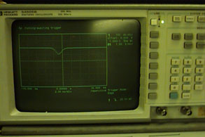
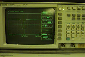
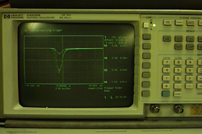
As you can see from the data, the phototube is very sensitive to the radioactive materials when placed on the scintillator. As the radioactive source gets close to the tube, the potential difference is significantly bigger. What does this mean? It means the scintillator works, otherwise the phototube could not have been so sensitive to the radioactive source. These are some graphic examples of the oscilloscope display. The first one is when there is no radioactive source placed on the scintillator. The second picture is when there is a radioactive source placed on the scintillator. The third is just a display of all results. The fourth one is just the setup for the test.
|
|
|
|
|
|
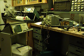
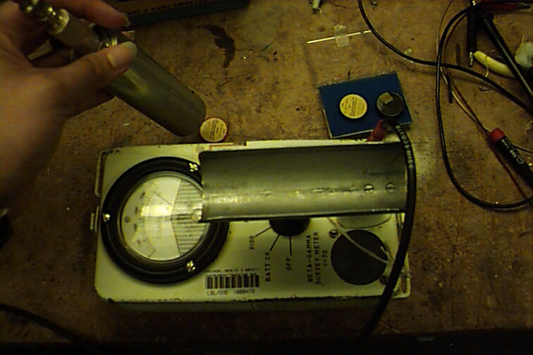
This is just a picture of when I used the Geiger-tube to
test the radioactivity of the radioactive source.